A UV sterilizer for a recirculating aquaculture system (RAS) should be selected from four operating conditions: actual treatment flow, target UV dose, minimum UV transmittance and installation layout. Tank volume and lamp wattage are useful inputs, but neither can determine the equipment size alone.
Because RAS water is continuously reused, waterborne microorganisms can circulate between tanks and treatment units. UV provides continuous physical disinfection without adding a chemical disinfectant or leaving a disinfectant residual in the treated water. Its job is to reduce susceptible microorganisms passing through the reactor; the biofilter and solids-removal equipment continue to manage the other water-quality loads.
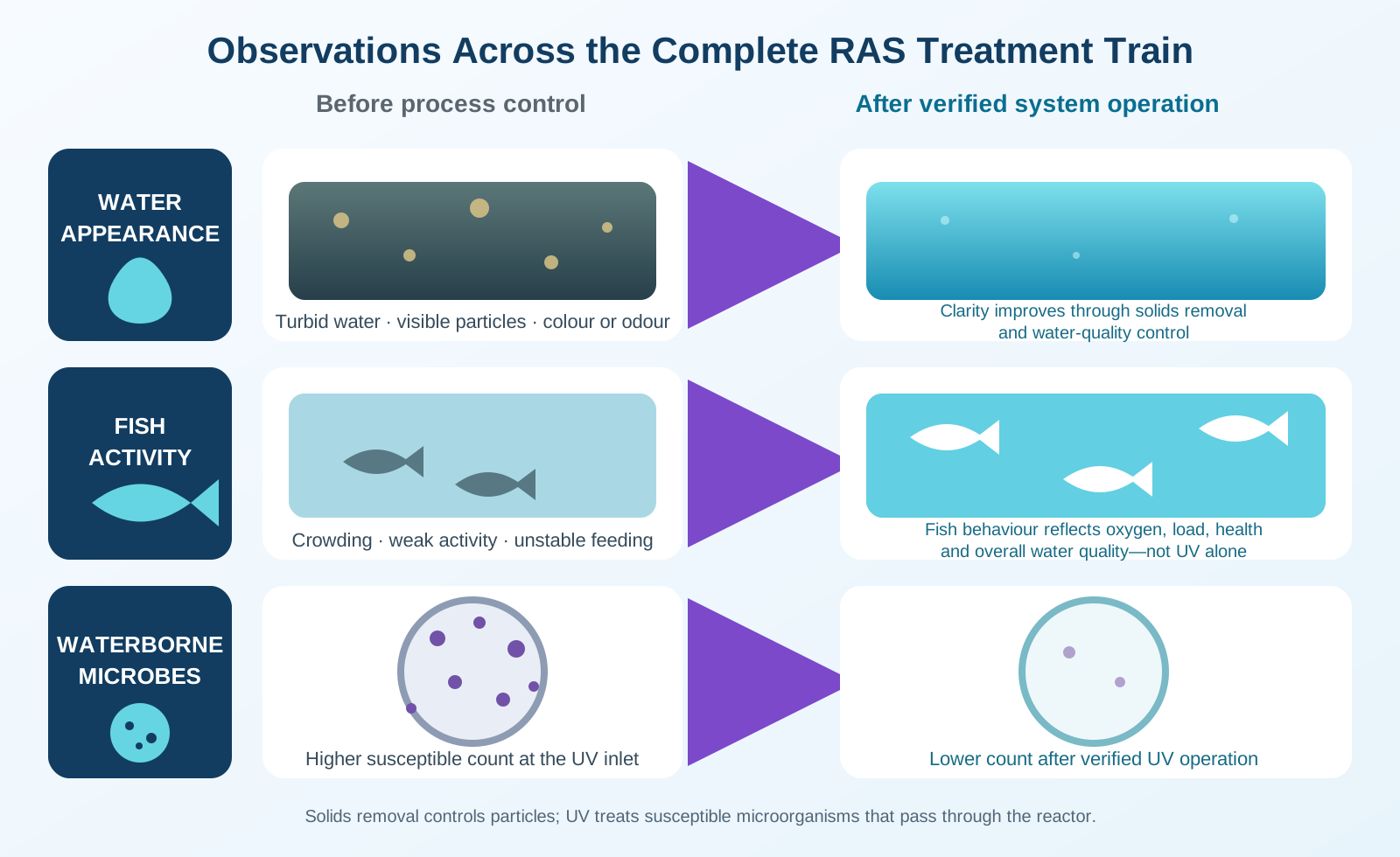
The practical sequence from selection through operation is:
- calculate the flow that will pass through the UV unit;
- define the microorganisms or biosecurity target;
- check water clarity and UV transmittance;
- select the reactor and lamp configuration;
- install the unit after effective solids removal;
- confirm the operating setpoints during commissioning; and
- maintain the delivered UV performance throughout operation.
This guide explains each step in the same order.
1. Calculate the actual flow through the UV sterilizer
Start with the system volume and circulation period.
For example, if a RAS contains 1,000 m³ of water and the design circulation period is two hours:
Circulation flow = 1,000 m³ ÷ 2 h = 500 m³/h
If the complete return flow passes through the UV reactor, the UV duty flow is 500 m³/h. If the UV unit is installed on a 150 m³/h side stream, the duty flow is 150 m³/h. If it treats only incoming makeup water, use the maximum makeup-water flow.
These are three different duties:
| UV duty | Flow used for selection | Main purpose |
|---|---|---|
| Intake or makeup-water treatment | Maximum incoming flow | Reduce the introduction of waterborne microorganisms |
| Full-flow recirculation treatment | Maximum return flow through the UV line | Treat the circulating water before it returns to production |
| Side-stream treatment | Actual branch flow | Repeatedly treat part of the circulating water |
Do not use daily makeup volume to size a full-flow recirculation unit. Do not use total tank volume as if it were an hourly flow rate. First identify the pipe or channel where the UV will be installed, then measure or calculate the maximum flow at that point.
2. Set the target UV dose for the organisms you need to control
Once the flow is known, define the treatment target. UV-C light around 254 nm inactivates microorganisms by damaging their genetic material. The required dose depends on the organism: common bacteria are generally easier to inactivate than resistant viruses, spores or parasites.
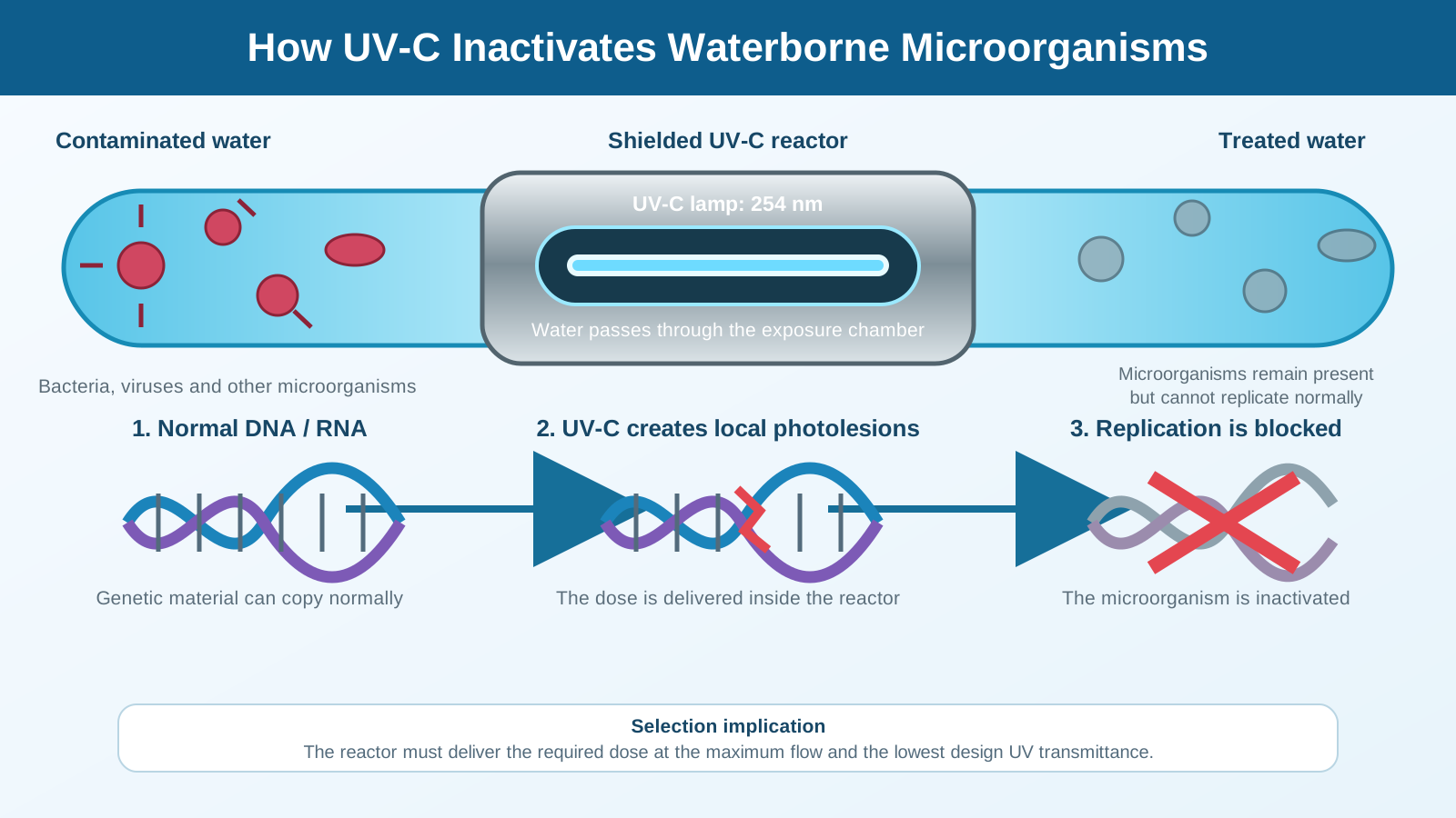
The design question is therefore not “How many watts do I need?” but:
What UV dose must the reactor deliver at the maximum flow and the lowest expected water quality?
For an aquaculture project, identify:
- the cultured species and life stage;
- the main bacterial, viral or parasitic risks;
- whether the duty is routine microbial-load control or a defined biosecurity barrier;
- the required reduction target; and
- whether the requirement comes from a farm protocol, aquatic-animal health specialist or project specification.
A dose value is an energy-per-area requirement, usually expressed in mJ/cm². It cannot be converted directly into lamp watts. Lamp power, reactor geometry, hydraulic residence time, UVT, sleeve fouling and lamp aging work together to determine the dose delivered by the complete reactor.
Indicative UV dose ranges for aquaculture selection
The following ranges provide an initial engineering reference for the organisms listed. Use each range as a preliminary selection input. The final project dose must specify the target organism, required log reduction, water matrix and test basis.
| Target microorganism | Preliminary UV dose range |
|---|---|
| Escherichia coli | 10–40 mJ/cm² |
| Vibrio spp., including V. parahaemolyticus | 20–60 mJ/cm² |
| Pseudomonas spp. | 30–80 mJ/cm² |
| Bacillus spp. | 100–200 mJ/cm² |
| Grass carp hemorrhagic disease virus | 100–200 mJ/cm² |
| Infectious hematopoietic necrosis virus (IHNV) | 150–300 mJ/cm² |
| Infectious spleen and kidney necrosis virus (ISKNV) | 120–250 mJ/cm² |
| Trichodina spp. | 50–150 mJ/cm² |
| Ichthyophthirius multifiliis | 150–300 mJ/cm² |
| Dactylogyrus spp. | 80–180 mJ/cm² |
For a preliminary budget, use a supplier's reference configuration with comparable flow, UVT and target dose. Final selection should use the reactor's stated performance at the project duty.
3. Check whether the water allows UV light to reach the target
After the dose is defined, check the water entering the UV unit. Suspended solids, algae, organic matter and colour absorb or scatter UV light. Microorganisms can also be shielded by particles.
For this reason, UV should normally follow effective solids removal. In a RAS, the upstream process may include a drum filter, microscreen, sand filter, protein skimmer or another suitable separation step. The correct combination depends on the farm and water conditions.
Measure UV transmittance at 254 nm (UVT254) at the proposed UV inlet. Ask the laboratory to report the optical path length with each UVT254 result. Use the lowest realistic UVT during feeding, cleaning, peak biomass and other demanding operating periods. A reactor selected at clean-water conditions may be undersized when the farm reaches full load.
The equipment supplier should therefore receive:
- minimum and maximum flow;
- minimum expected UVT254;
- turbidity or suspended-solids data;
- salinity and temperature;
- pipe size or channel dimensions; and
- the target UV dose.
If water quality changes widely, include a UV intensity sensor, flow measurement and alarm logic so the operator can see when the unit moves outside its intended operating range.
Should an RAS use UV, ozone, or both?
Choose by treatment duty, not by ranking one technology as stronger. Use UV when the defined task is to reduce susceptible microorganisms that pass through a reactor at a verified dose. Consider ozone when the project also requires controlled oxidation of dissolved or suspended organic matter, colour or odour.
Ozone needs its own contact, off-gas, residual-ozone removal, monitoring and safety design. Residual ozone must be removed before treated water returns to the animals. Seawater systems also need checks for residual oxidants and harmful ozonation by-products before water returns to the animals.
Using both is justified only when both treatment duties have been defined. It is not automatically better. Document what each stage must achieve, test the actual water, and design around flow, organic load, target organisms and residual-oxidant control.
Can UV remove dissolved organic compounds?
No. A conventional germicidal UV reactor should not be selected as a dissolved-organics removal process. Its primary job is to inactivate susceptible microorganisms. Dissolved organic matter can instead absorb UV and reduce UVT, making the required microbial dose harder to deliver.
Mechanical filtration removes suspended particles but does not necessarily solve dissolved-organic accumulation. If dissolved organics are a design problem, measure the water and select an appropriate oxidation or separation process. Controlled ozonation can transform parts of the dissolved-organic matrix, but performance depends on the water composition and dose and still requires residual-ozone and safety controls. Size the UV reactor using the water quality expected after pretreatment; do not use higher lamp wattage as a substitute for treating the organic load.
4. Select the reactor type and lamp configuration
With flow, dose and water quality defined, compare the available UV arrangements.
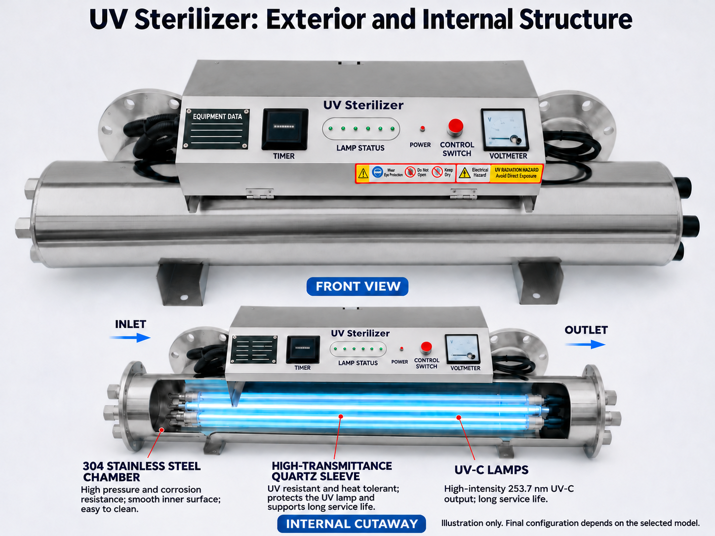
Compare the two common aquaculture arrangements by water-flow control, installation, monitoring and maintenance conditions.
| Selection item | Flow-through UV | Submersible UV |
|---|---|---|
| Installation | Installed in a pipeline, normally in series downstream of the pump | Installed directly in a purpose-built tank, sump or pond zone |
| Water-flow control | Controlled flow and more uniform contact time | Strongly affected by mixing, shielding and dead zones |
| Typical applications | RAS, hatcheries and industrial aquaculture | Small ponds, storage tanks or temporary treatment duties |
| Main advantages | Stable treatment duty and easier performance control | Simple arrangement and easier installation |
| Monitoring | Can integrate flow, UV-intensity, alarm and interlock signals | Monitoring is usually more limited and depends on the installation |
| Maintenance | Requires regular quartz-sleeve cleaning and service clearance | Requires protection against biofouling and careful placement |
| Relative cost | Generally higher | Generally lower |
| Selection guidance | First choice for industrial RAS where each treated water stream must receive a defined exposure | Use only when circulation, shielding and exposure are deliberately engineered; avoid assuming whole-pond treatment |
Closed-vessel flow-through UV
Water is forced through a closed reactor, so flow and exposure can be controlled. This is usually the first choice for pumped RAS pipework, hatcheries and indoor intensive aquaculture.
Check the pressure loss, flange or connection size, maximum operating pressure, sleeve-cleaning method and the space required to remove lamps and quartz sleeves.
Open-channel UV
Open-channel systems suit gravity channels and larger aquaculture-effluent flows. Selection depends on channel width, water depth, minimum and maximum flow, module arrangement and level control. The system must keep the lamps submerged and the hydraulic conditions within the design range.
Submersible UV
Submersible units can be useful in defined tanks, sumps or purpose-built chambers. They should not simply be placed in a stocked pond and assumed to treat the whole water body. Effective treatment still requires controlled water movement, safe shielding, electrical protection and maintenance access.
Low-pressure or medium-pressure lamps
Low-pressure high-output lamps are energy-efficient and suit continuous treatment where multiple lamps can be installed. Medium-pressure lamps provide high output from fewer lamps and can reduce the reactor footprint, but normally use more energy and produce more heat.
Choose between them by comparing the complete system at the required duty: delivered performance, number of lamps, energy use, footprint, cleaning arrangement, spare parts and maintenance time. Do not compare only the wattage of one lamp.
5. Install UV after solids removal and position it around the biofilter
The first placement rule is straightforward:
Put the UV where the water is clean enough for reliable transmission and where the treated flow cannot bypass the reactor during normal operation.
In many RAS layouts, the UV is installed after mechanical filtration. Its position relative to the biofilter depends on what the system is intended to protect.
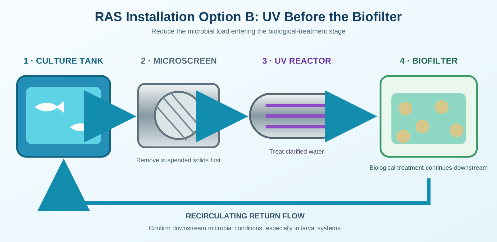
UV before the biofilter
This arrangement treats the water entering the biological-treatment stage. It can reduce the microbial load reaching that stage, but the biofilter and downstream pipework remain after the UV treatment point.
UV after the biofilter and before the culture tanks
This arrangement treats the return water closer to the production tanks. It is often selected when the main goal is to reduce the microbial load returning to the animals. The designer should check whether the biofilter releases particles that could reduce UV performance.
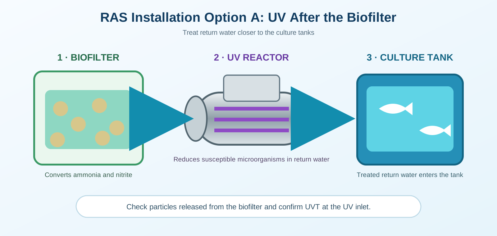
For larval systems, also account for bacterial regrowth and the microbial community the system is designed to maintain when choosing the UV position.
Confirm the position on the process drawing, check water quality at that inlet, and close unintended bypasses during normal operation.
UV does not replace the biofilter. The biofilter converts ammonia and nitrite; UV reduces susceptible microorganisms that pass through the reactor. The two processes solve different problems.
6. Define the operating limits during commissioning
Commissioning should confirm that the installed unit operates under the same conditions used for selection.
Record:
- minimum and maximum UV-line flow;
- normal UV intensity and alarm setpoint;
- UVT at startup and under loaded operation;
- valve positions for normal operation, isolation and bypass;
- pump status and interlocks;
- sleeve-cleaning procedure;
- lamp replacement basis; and
- the action required when intensity or flow moves outside the approved range.
An illuminated lamp only proves that the lamp is on. It does not prove that the required dose is reaching the water. Flow, UV intensity, sleeve condition and water quality must be considered together.
The UV alarm response must also protect the animals. Automatically stopping all RAS circulation may create a more immediate oxygen or water-quality risk. Decide in advance whether the correct response is an alarm, standby reactor, reduced flow, isolation of a production loop or another site-specific action.
7. Maintain UV performance as the farm load changes
During operation, scale, biofilm and mineral deposits can build up on the quartz sleeves. Lamp output also declines with operating time. Both reduce effective UV delivery even when the lamps still appear to be working.
A practical maintenance routine includes:
- checking UV intensity and flow records;
- inspecting and cleaning quartz sleeves;
- checking the UV sensor and automatic wiper, if fitted;
- replacing lamps according to the equipment’s rated service criteria;
- inspecting seals, connections and electrical components; and
- checking UVT again when water colour, feed load, biomass or source water changes.
Set the cleaning interval from actual fouling at the farm. A unit in hard freshwater, seawater or water with a high organic load may need a different schedule. Keep enough clearance to remove lamps and sleeves without dismantling nearby pipework.
Before requesting a quotation: prepare the UV selection data
Before purchase, bring the key inputs from this process into one selection table. Send the following data with the enquiry:
| Required information | Why it matters |
|---|---|
| Process flow diagram and proposed UV position | Confirms which water stream will be treated |
| Maximum, normal and minimum flow | Defines the hydraulic duty |
| Total system volume and circulation period | Checks the relationship between the farm and UV-line flow |
| UVT254, turbidity and suspended solids | Shows how much UV light can pass through the water |
| Cultured species, life stage and target organisms | Supports selection of the treatment dose |
| Freshwater, brackish water or seawater | Determines wetted-material and cleaning requirements |
| Pipe size, pressure or channel dimensions | Defines the reactor connection and hydraulic layout |
| Power supply, controls and alarm requirements | Defines the electrical and automation scope |
| Maintenance space and standby plan | Keeps the system serviceable without losing essential circulation |
Send these operating data to KONCHE for a UV equipment selection assessment. For the general sizing method, see How to Size a UV Water Treatment System. For available equipment, see KONCHE UV Water Sterilizers.
Technical references
- Roy P. E. Yanong, Biosecurity in Aquaculture, Part 2: Recirculating Aquaculture Systems, SRAC 4708, 2012.
- Vadstein et al., K-Selection as Microbial Community Management Strategy, 2018.
- Aquaculture UV reference table supplied for this article, 2026.
- Roy P. E. Yanong, Fish Health Management Considerations in Recirculating Aquaculture Systems—Part 2: Pathogens, UF/IFAS Extension, revised 2009 and reviewed 2019.
- Aguilar-Alarcón et al., Impact of ozone treatment on dissolved organic matter in land-based recirculating aquaculture systems, Science of the Total Environment, 2022.