A glowing lamp or green power light does not prove that a recirculating aquaculture system is receiving the required UV treatment. Effective performance depends on UV output reaching the water, actual reactor flow, water quality and UVT, clean optical surfaces, correct sensor operation, and a layout that prevents untreated bypass or downstream recontamination.
For a commercial RAS, troubleshoot in this order: protect fish life support and personnel; identify the exact alarm; verify flow, valves and bypass; check water quality, sleeves and sensors; review lamp, ballast and electrical status through the manufacturer’s procedure; then verify recovery with operating data and, where required, microbiological results.
Why “lamp on” is not enough
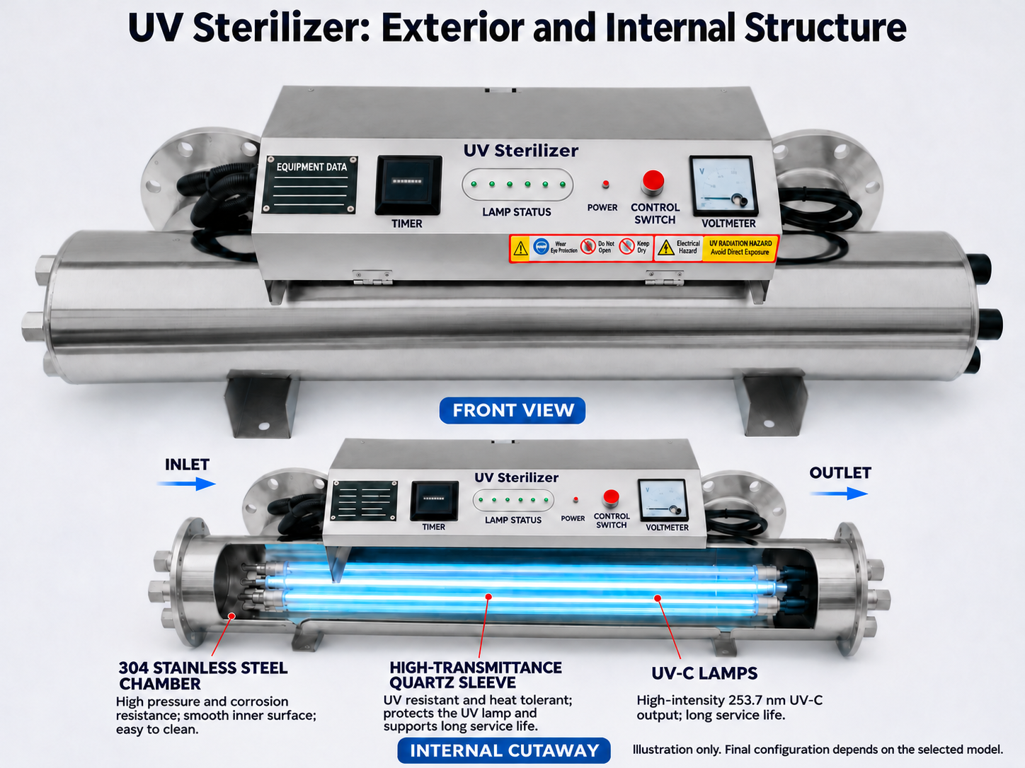
A status light or visible glow confirms only a limited condition: the controller or lamp may be energized. It does not confirm delivered dose. The Pentair BioShield manual, for example, states that its relative UV-intensity measurement is not a UV-dose measurement.
Performance can fall while lamps appear on because:
- branch flow has increased or water is bypassing the reactor;
- UVT has fallen or particles shield microorganisms;
- quartz sleeves or the sensor window are fouled;
- lamps have aged or a ballast, power supply or connection has a fault;
- the sensor is dirty, misinstalled or out of calibration;
- the display shows intensity rather than dose; or
- treated water is recontaminated downstream.
Before troubleshooting: stabilize the RAS safely
UV is part of the treatment train, but pumps, oxygenation, degassing and biofiltration may be critical life-support functions. Do not shut down the whole circulation loop as a reflex unless the site emergency plan requires it.
- Record the exact alarm without changing its setpoint.
- Note the time, displayed intensity or dose, flow, UVT and lamp status.
- Check fish behavior, dissolved oxygen, temperature and critical life-support alarms.
- Identify whether the UV branch can be isolated without stopping essential circulation.
- Direct off-spec or untreated discharge according to the contingency plan.
- Prevent personnel from viewing exposed UV lamps or opening energized or pressurized equipment.
If there is leakage, a broken sleeve, electrical damage, overheating or a manufacturer-defined shutdown alarm, stop the affected UV equipment according to the manual and call qualified service personnel.
Symptom-to-action table
| Symptom | Likely cause families | Check first | Appropriate next action |
|---|---|---|---|
| Low-intensity alarm after stable operation | UVT change, sleeve/sensor fouling, lamp aging, changed flow | Trend UVT, flow and intensity together | Correct water or flow; clean and inspect only under safe isolation; follow model-specific lamp checks |
| Lamp status on but microbial result worsens | Excess flow, poor UVT, shielding particles, bypass, wrong sample point, recontamination | Actual branch flow, valve positions, inlet water and sampling route | Restore validated conditions and repeat verification at defined points |
| Intensity reading jumps or is implausible | Sensor fouling, air, installation or calibration issue | Sensor status, installation and process stability | Follow the manufacturer’s procedure; do not tune the alarm to hide the symptom |
| Performance falls after backwash or harvest | Solids breakthrough or a short flow peak | TSS/turbidity, UVT and instantaneous flow | Stabilize upstream filtration or equalize the peak |
| Flow through the UV branch falls | Clogged strainer/filter, valve, pump or headloss change | Measured flow and pressure trend | Remove the hydraulic restriction through the site maintenance procedure |
| Alarm remains after sleeve cleaning | Sensor, lamp/ballast, UVT or baseline issue | Clean-state readings, lamp status, sensor and water data | Escalate with records; replace or recalibrate only as specified |
| Good reactor reading but poor downstream sample | Recontamination, stagnant storage, dirty downstream piping, sampling issue | Compare outlet and final-point samples | Investigate the downstream route and sampling plan |
A six-step diagnostic sequence
Step 1: identify the real failure signal
Write down exactly what changed: low intensity, low calculated dose, lamp or ballast alarm, end-of-life warning, temperature, flow, microbial result or an operator observation. These signals are not interchangeable. Do not lower an alarm threshold simply to clear the display.
Step 2: verify actual flow and the hydraulic route
Start with measured flow through the reactor or branch—not pump nameplate flow or a VFD percentage. Check the approved operating envelope, valve positions, bypass leakage, parallel-reactor flow split, clogged strainers, pump changes, trapped air and whether the reactor is completely flooded. Excess flow can reduce exposure; inadequate or lost flow may create equipment risks depending on design.
Step 3: check water quality and UVT
Compare current inlet water with the commissioning baseline: UVT measured by the same method and path length, turbidity or TSS, color and UV-absorbing constituents, filter differential pressure, backwash performance, feed or biomass events and source-water changes. WOAH guidance notes that suspended solids reduce UV transmission and effectiveness. Correct the upstream process rather than recalibrating the display to a poor water condition.
Step 4: distinguish sleeve fouling from sensor fouling
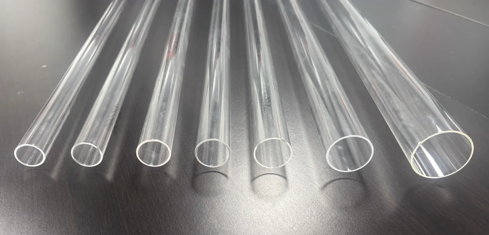
Quartz sleeves transmit UV into the water. Mineral, organic or biological deposits reduce transmission, while a fouled sensor window can report a falsely low value. A gradual decline is often consistent with fouling or lamp aging; a sharp change after an event suggests flow, UVT, air or configuration. One bank differing from the others points to a local lamp, ballast, sensor or fouling condition.
Step 5: review lamp, ballast, power and sensor status
A lamp can emit visible light after useful UV output has declined. Conversely, a low reading can be caused by the sensor or water rather than the lamp. Review operating hours and switching history, individual lamp and ballast status, voltage or temperature alarms, recent replacements, connector alarms, warm-up time, calibration and replacement-part specification. The Sterilight Silver Owner’s Manual lists dirty sleeves, dirty or incorrectly installed sensors, changed water quality, lamp problems and monitor malfunction among possible low-intensity causes. Thresholds and service procedures remain model-specific.
Step 6: check for recontamination and verify recovery
UV treats only water that passes through the reactor. It does not remove organisms protected in tank or pipe biofilms, settled solids, dead zones or untreated branches. Nets, hoses, hands, splashing and shared equipment can also transfer contamination. Where the site plan allows, compare inlet, outlet and downstream control-point samples, and review sampling timing, transport and laboratory method.
How to return the UV system to normal service
- Restore the approved valve and flow configuration.
- Confirm the reactor is fully flooded and free of trapped air as required by the manual.
- Allow the specified lamp warm-up and sensor stabilization time.
- Confirm individual lamp and ballast status.
- Record flow, UVT, intensity or calculated dose against the clean commissioning baseline.
- Test the relevant alarm and interlock without defeating safety functions.
- Confirm that no untreated bypass remains open.
- Complete microbiological verification when required by the biosecurity, customer or regulatory plan.
Do not declare recovery based only on the alarm disappearing. The return-to-service record should connect the corrected cause to restored process conditions.
What to send the supplier when the problem persists
- reactor model, serial number and controller software version;
- exact alarm text and timestamp;
- intensity or dose trend before and after the event;
- actual UV-branch flow and how it was measured;
- UVT result, method and sample point;
- turbidity/TSS and recent upstream changes;
- lamp and ballast status plus operating hours;
- last sleeve, sensor and lamp service dates;
- installation and controller photos taken without UV exposure;
- valve and bypass arrangement, recent replacement parts; and
- microbiological sample points and results, if relevant.
Do not send only “the lamps are on but UV is not working.” A time-aligned flow, UVT and intensity record is far more useful.
Preventing repeat failures
Build a baseline for normal production, harvest, backwash and seasonal source-water changes, and trend flow, UVT and intensity together. Maintain upstream solids removal, inspect for recurring fouling instead of relying only on a fixed calendar, control alarm and calibration changes, retain approved spares where downtime risk justifies them, protect service clearance and train operators to distinguish lamp status, UV intensity, UVT and delivered dose.
KONCHE can assist with a flow-through UV system review when operating data, water quality and installation arrangement are available. Troubleshooting should remain tied to the specific reactor manual and the RAS biosecurity plan.
Frequently asked questions
The green light is on. Is the water being disinfected?
Not necessarily. Confirm actual flow, UVT, optical cleanliness, lamp and ballast status and the monitored performance value. A status light is not dose verification.
Why does UV intensity move while the lamps stay on?
Possible causes include changing UVT, flow, bubbles, sensor-window fouling, an unstable signal or lamp and ballast behavior. Compare time trends before cleaning, recalibrating or replacing parts.
Should we replace the lamps first?
Not automatically. Review hours, individual alarms, water quality, sleeve and sensor condition, and flow. Replacing a lamp will not fix a dirty sensor, open bypass or low UVT.
How soon should microbial results improve after restoring UV?
There is no universal time. It depends on treatment objective, turnover, system volume, sampling point and whether organisms persist in biofilms or untreated parts of the RAS.
Can we keep operating during a low-intensity alarm?
Follow the contingency plan and reactor manual. Protect critical fish life support, but do not treat off-spec UV water as verified. The response may involve isolating the UV branch, using standby capacity, holding discharge or changing operating flow.
Related KONCHE resources
Use these pages to confirm the original selection basis before changing equipment or operating limits.
Duty flow, UVT, target, placement and commissioning inputs.
Read the guide →MAINTENANCE SUPPORTUV Disinfection ConsumablesLamps, ballasts, quartz sleeves and sensors matched by equipment data.
View consumables →SERVICE REVIEWReview a Persistent UV FaultSend the alarm, flow, UVT, trend and installation data for an engineering review.
Start project review →